Electrical Design & Build
Contacts, Connectors, and Crimps
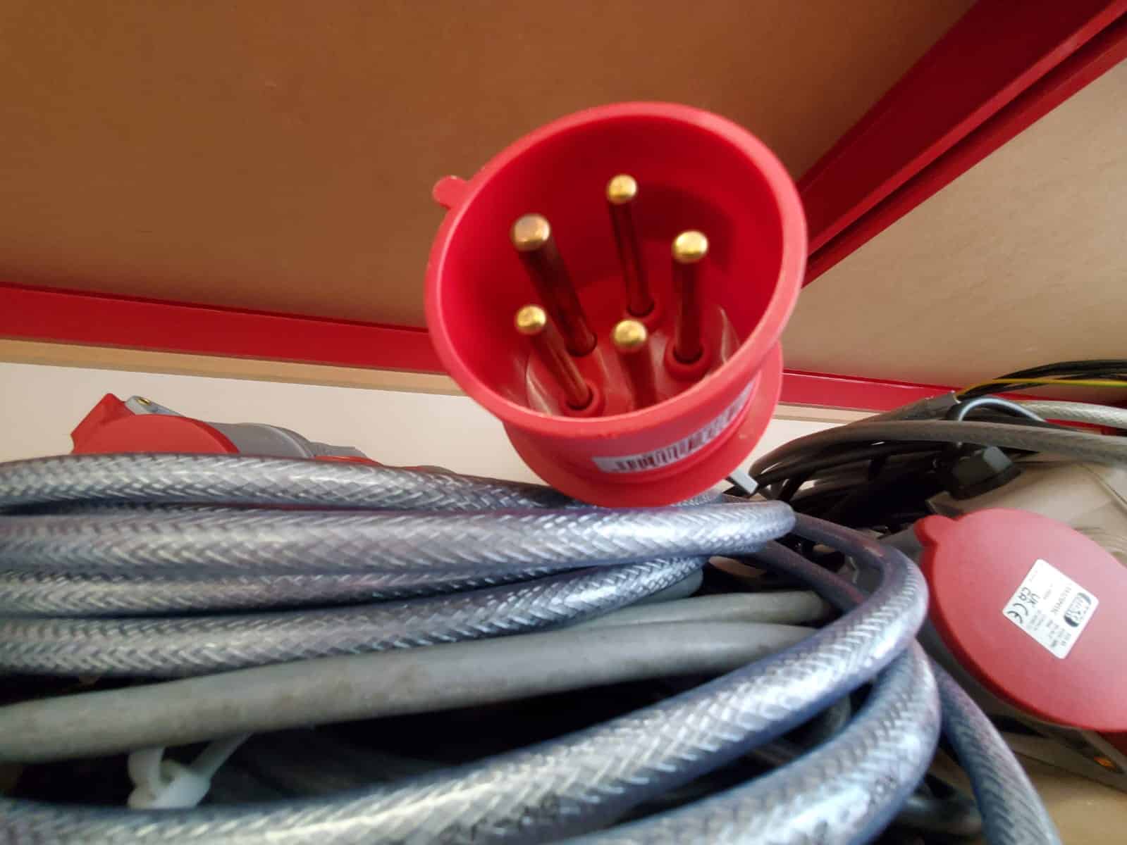
Male Pins & Female Sockets
- Pin Contacts (Male): Protruding pins that fit into female receptacles.
- Socket Contacts (Female): Recessed, spring-loaded contacts that receive the male pins.
- Crimp Contacts: Used for reliable, solder-less connections.
Contacts, Connectors, and Crimps
Contact Materials (The Conductive Elements)
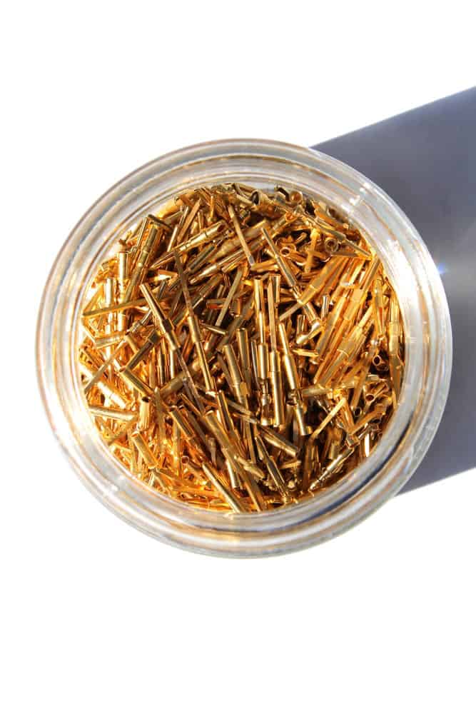
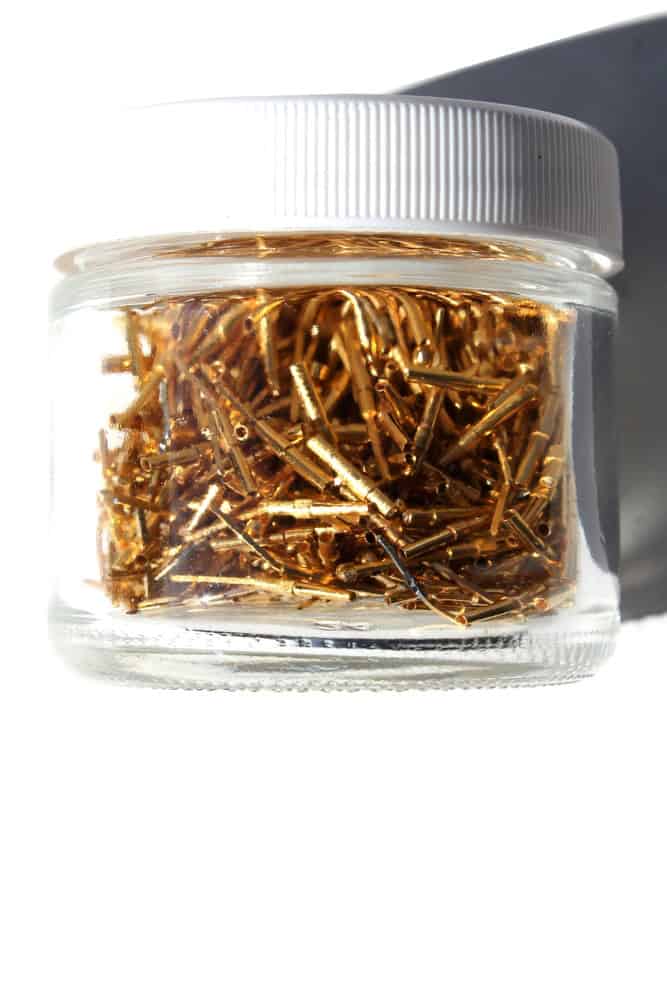
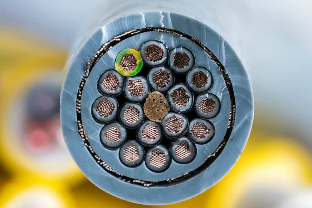
Contacts are the core conductive elements, typically made of brass or phosphor bronze, and plated to improve conductivity and resist corrosion.
- Copper/Brass: Commonly used for base conductivity, often tin-plated for cost-effective, durable connections.
- Silver/Silver-Nickel: Used in industrial, high-temperature, or high-current, demanding environments for optimal, long-lasting conductivity.
- Gold Plating: Often used in sensitive electronics or data applications for superior oxidation resistance.
The following slides will show you some examples of both the Male & Female Contacts, as well as Silver & Gold plated Contacts.
Contacts, Connectors, and Crimps
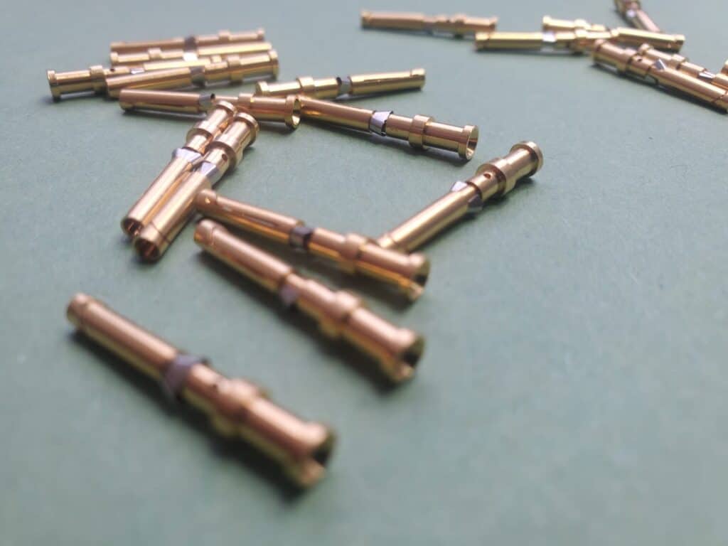
CDFD 0.5
This part is an ILME Contact Pin:
It is Female.
It is Gold Plated, for Optimal Conductivity and Anti-Corrosion.
It is 10 Amp, used in Plugs & Sockets passing up to 10 Amps of Current.
It is 20 Awg, which stands for American Wire Gauge. Used since 1857, this System indicates wire thickness accommodated by the Contacts & Connectors, with smaller gauge numbers indicating thicker wire accommodation.
Contacts, Connectors, and Crimps
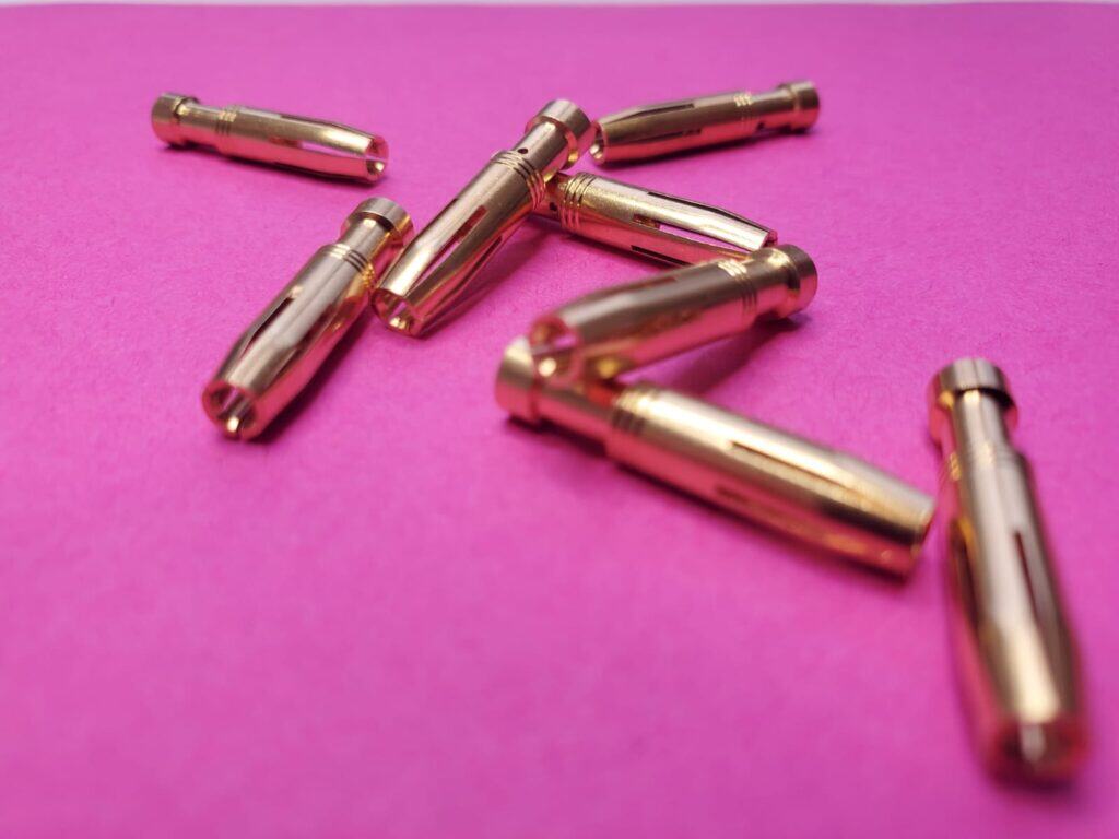
CCFD 2.5
This part is another ILME Contact Pin:
It is also Female.
It is Gold Plated, similarly to the previous example.
It is 16 Amp, used in Plugs & Sockets passing up to 16 Amps of Current safely.
It is 14 Awg, which means that it can house wires thicker than the previous example.
Contacts, Connectors, and Crimps
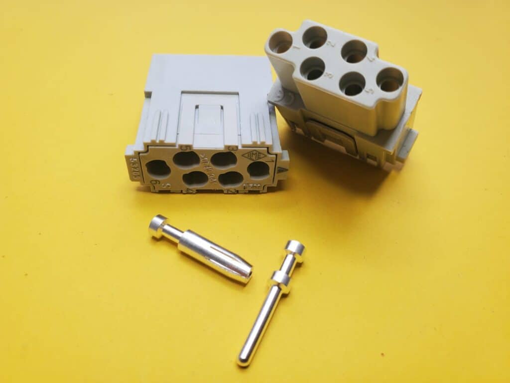
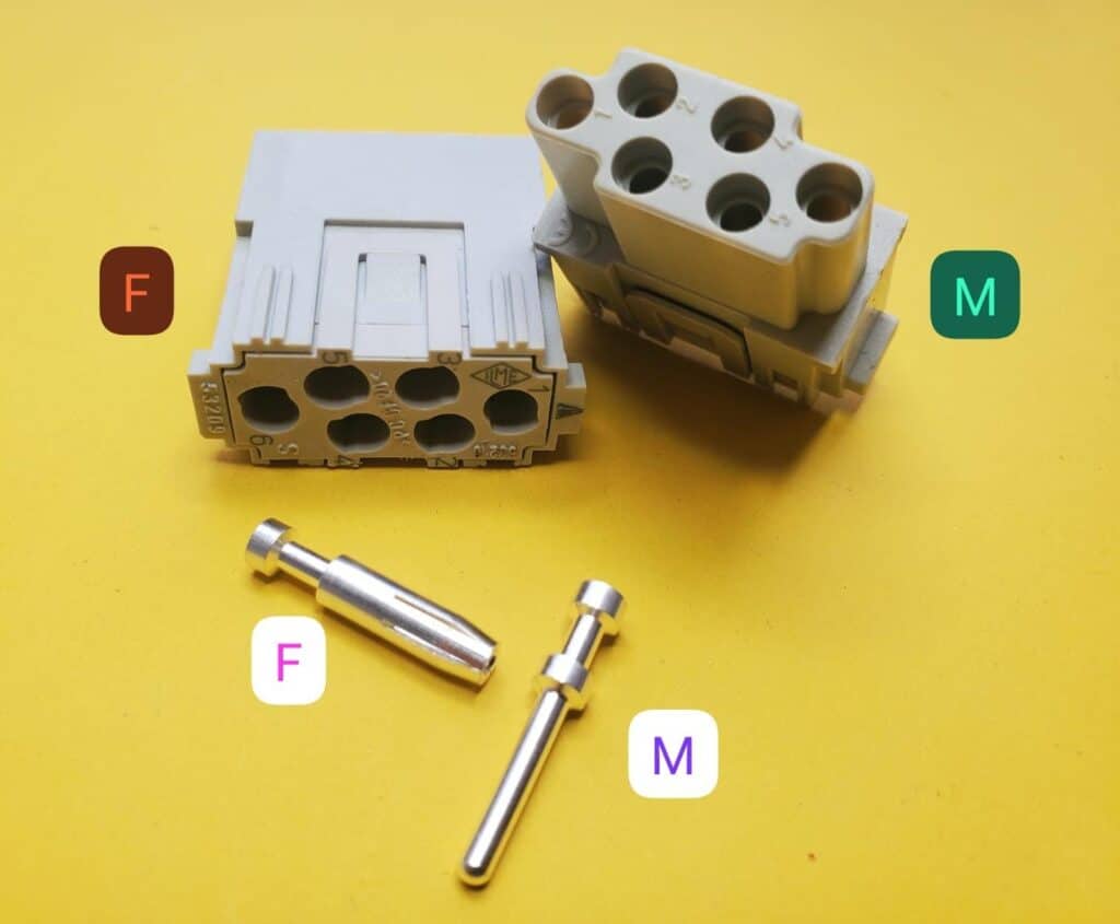
CCFA 0.5 & CCMA 0.5
By this slide, if you’ve an eagle eye and an inquisitive mind, you may have a question along these lines:
Hang on a minute! Those Contacts look different, but they’re both Female?
Are you sure? Did you mean to say that CDFD 0.5 is Male, and CCFD 2.5 is Female?
That would make more sense, as the latter appears to be a Receptacle, whilst the first appears to be a Pin?
Did you have such a question to ask? Are you like I am?
Male & Female in the context of Contacts used in the production of Plugs & Sockets, refers to the final destination of the Contacts – i.e. it hasn’t anything to do with how they appear to the naked eye, rather it refers to whether or not the Contacts are to be fitted into a Plug or a Socket.
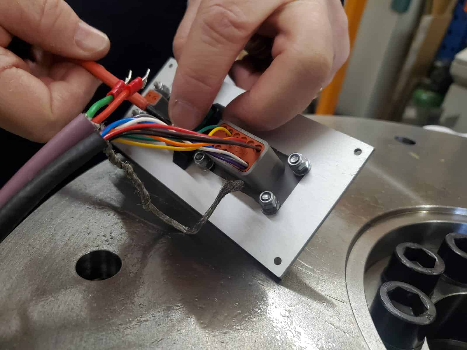
By way of example, this image shows a CCFA 0.5, a CCMA 0.5, a Plug, and a Socket.
Contacts, Connectors, and Crimps
Contacts, Plug, and Socket
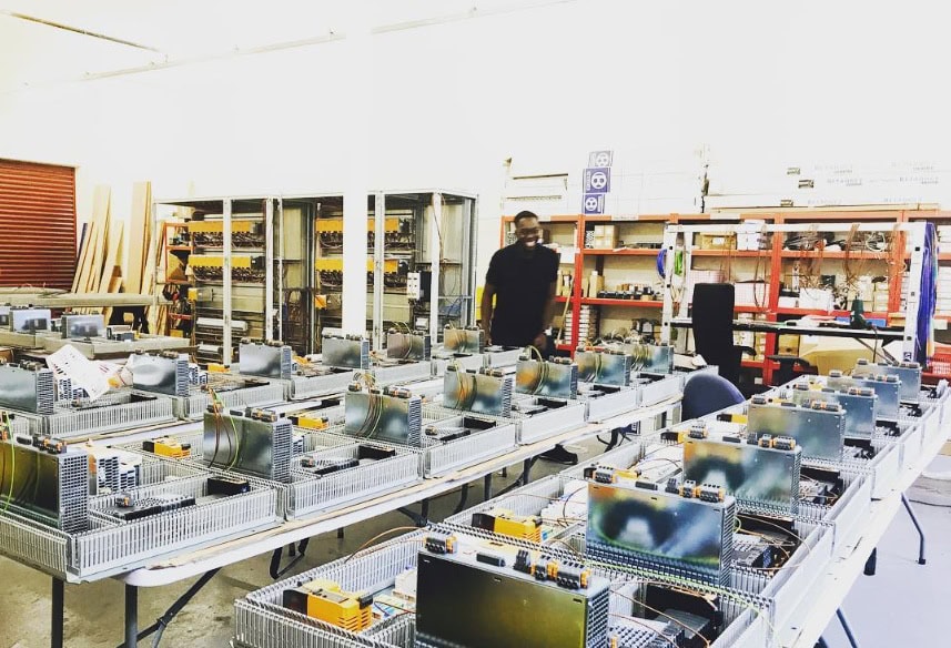
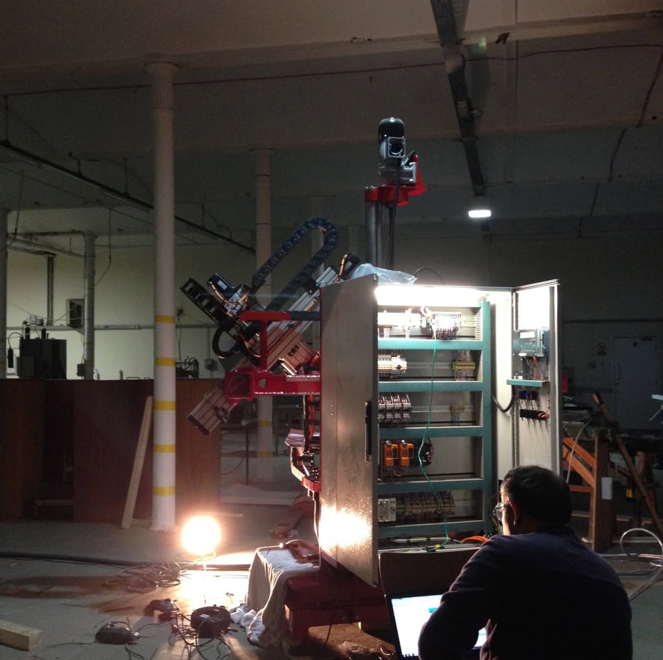
Control Cabinet Build
What it takes to build a robust & tidy Control Cabinet at 2M
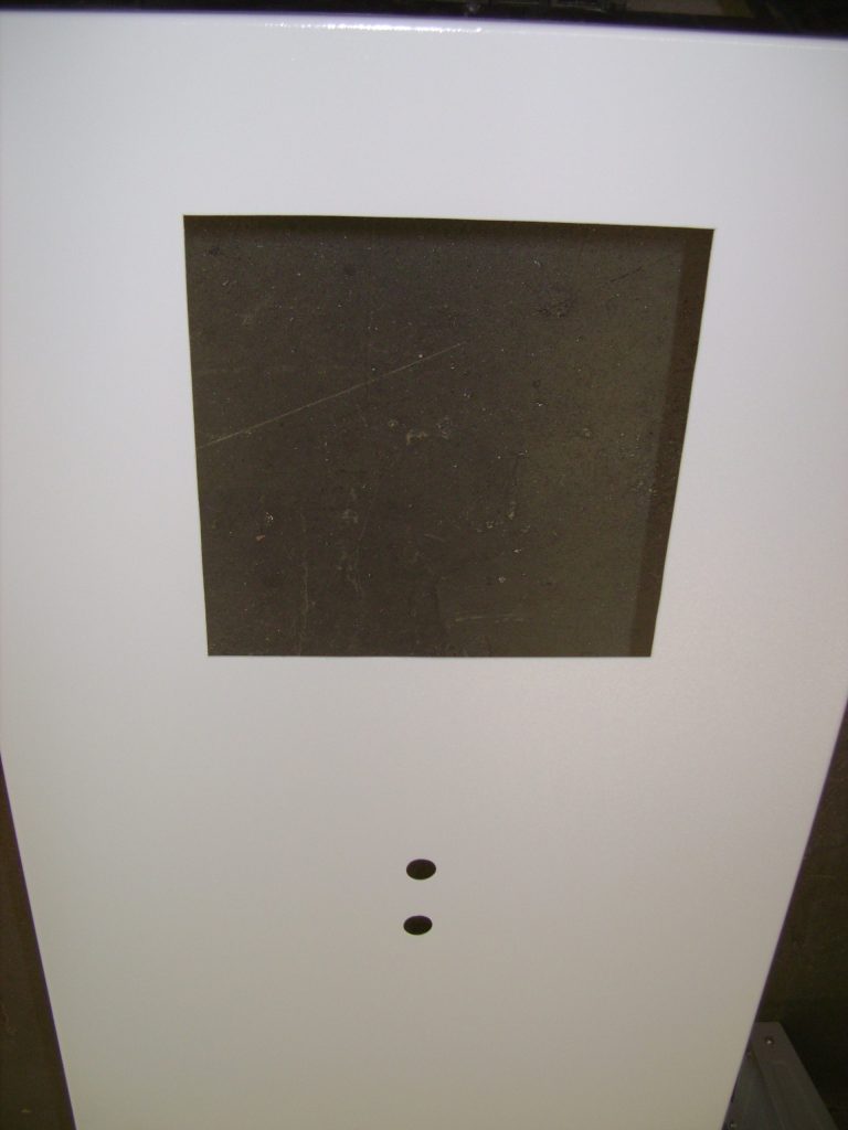
Here we are on Day 1.
The enclosure door is marked ready for cut-out in accordance with the electrical panel-drawings layout details which you can also see in this photo.

Control Cabinet Build
Here’s the complete panel cut-out using jigsaw and metal hole-punches.
All bare edges have been dressed and painted with the relevant RAL colour.
Control Cabinet Build
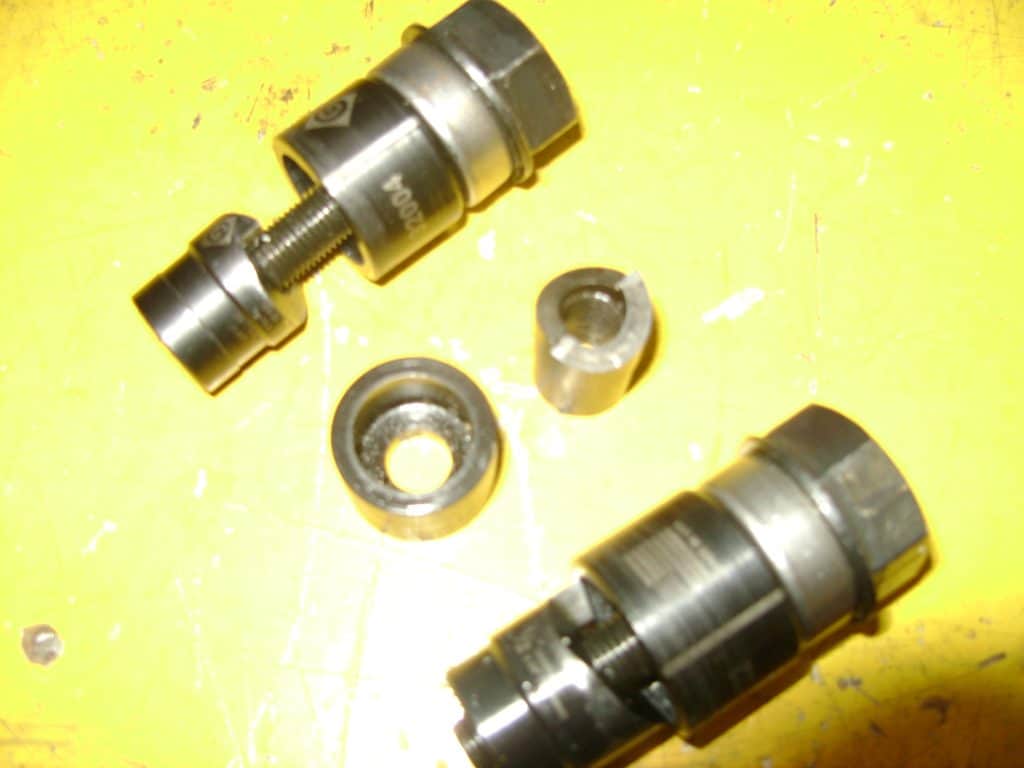
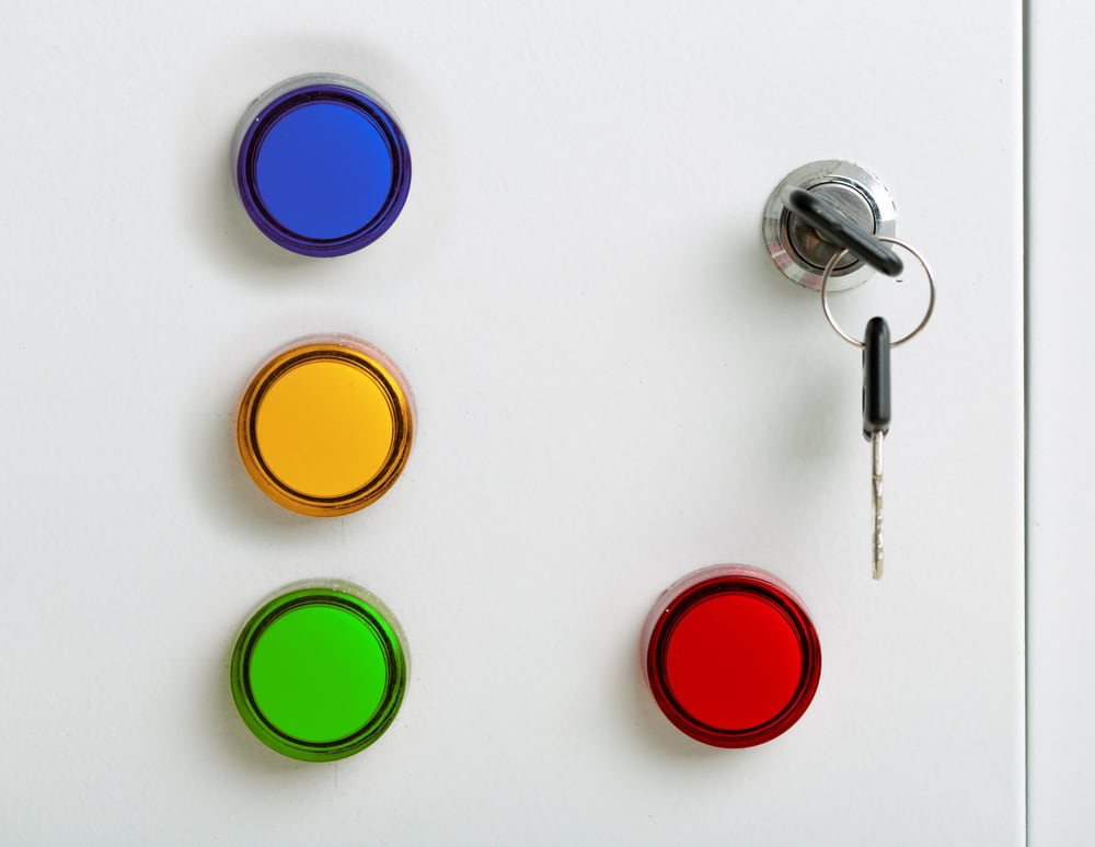
Here are the handy hole-punches used to make the holes for push-buttons and lamps fitted in the cabinet doors.
Look out for our upcoming updates next week including “arm fitting” and much more.
Control Cabinet Build
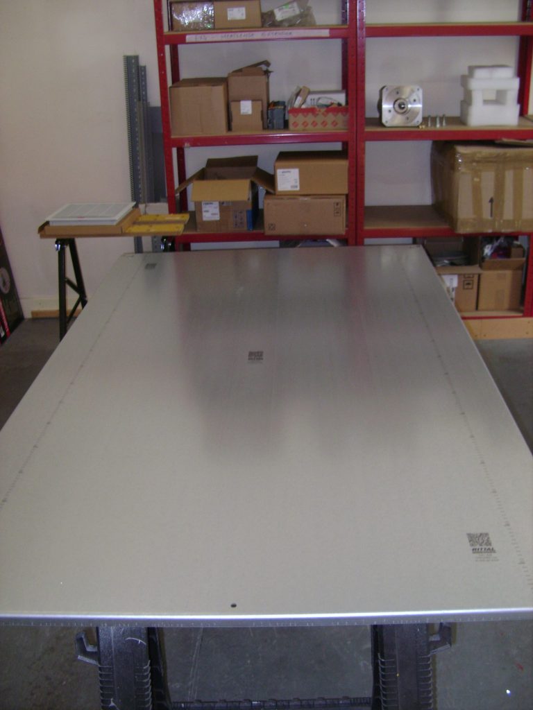
Here is our empty control panel. This one is made out of mild steel, sprayed to a standard RAL colour.
Cabinet specifications meet client requirements, taking into consideration environmental site factors.

Control Cabinet Build
Rounding up Day 1, here’s the back-plate which has been removed from the cabinet, ready to be laden and fitted with components.
Control Cabinet Build
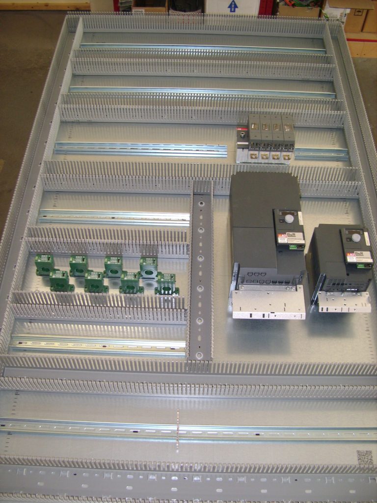
On Day 2, we can see the removed back-plate with components laid out according to the electrical layouts, ready for marking and drilling.
Control Cabinet Build
At the end of Day 2.
The back-plate is beginning to take shape with fitted components in accordance to the parts-list and refitted into the control cabinet ready for wiring.
Control Cabinet Build
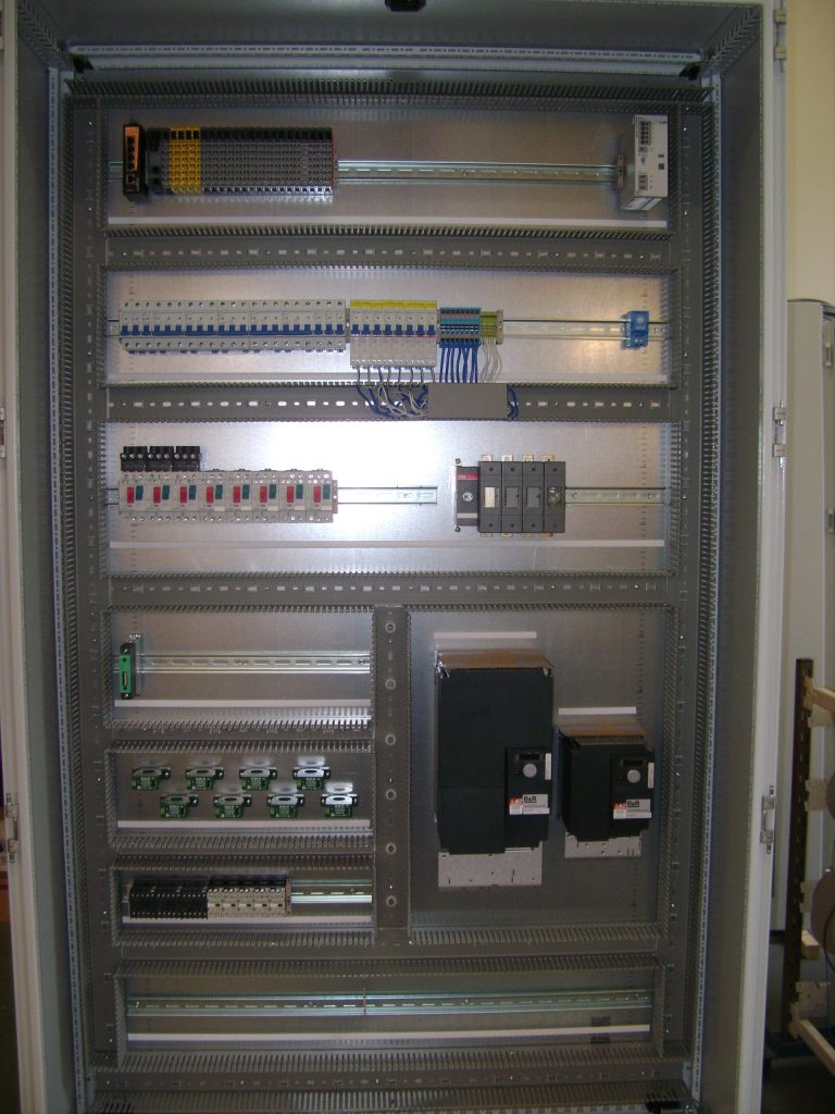
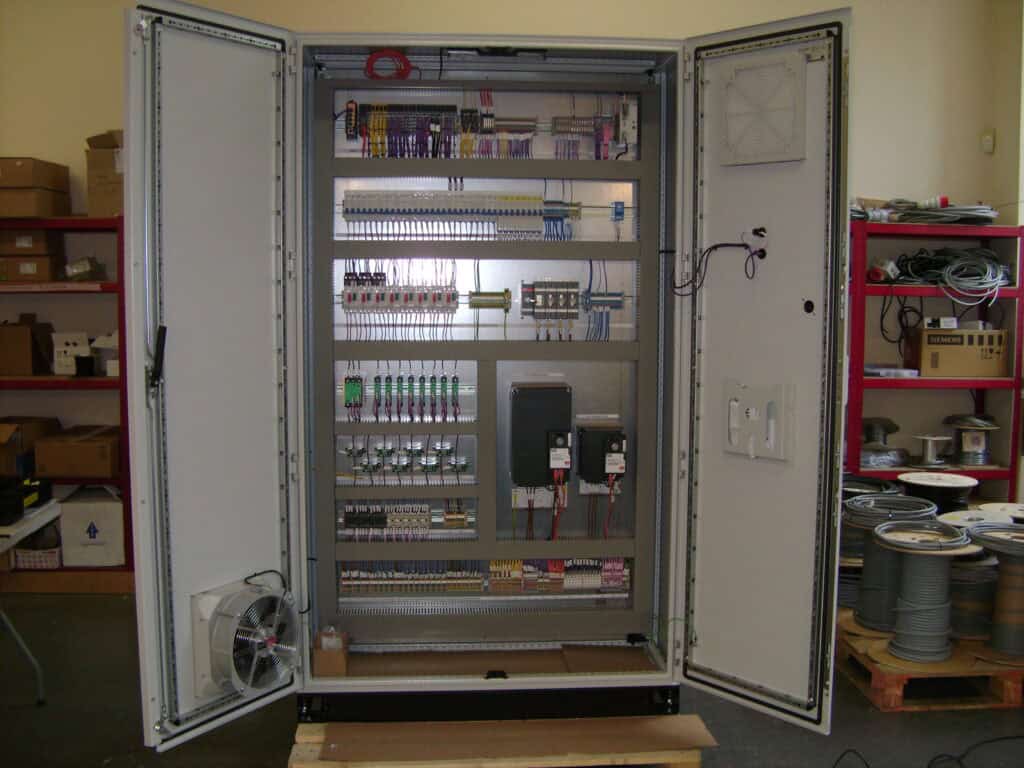
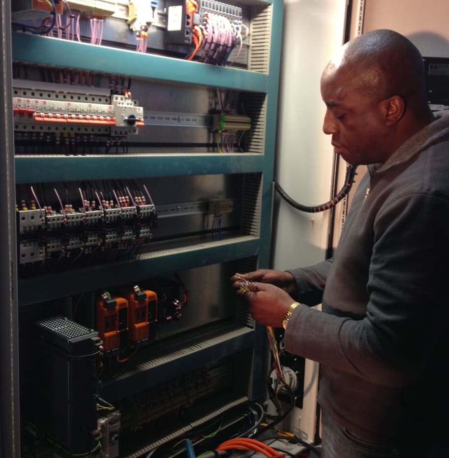
Here we on Day 4.
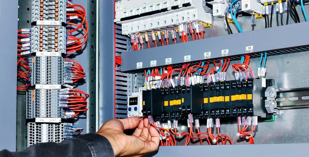
All the A/C (alternating current) wiring is complete.
At a glance, you may notice a:
- PLC (Programmable Logic Controller)
- Circuit breakers
- Contactors
- Drives
- Fuse Switch
Control Cabinet Build
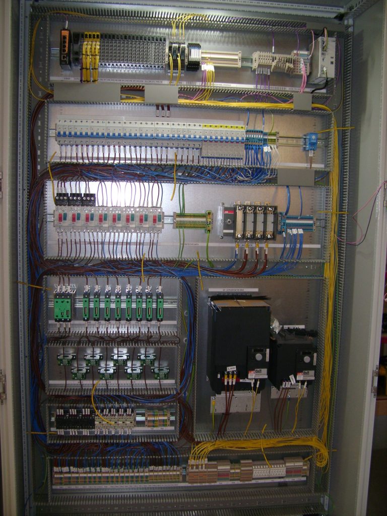
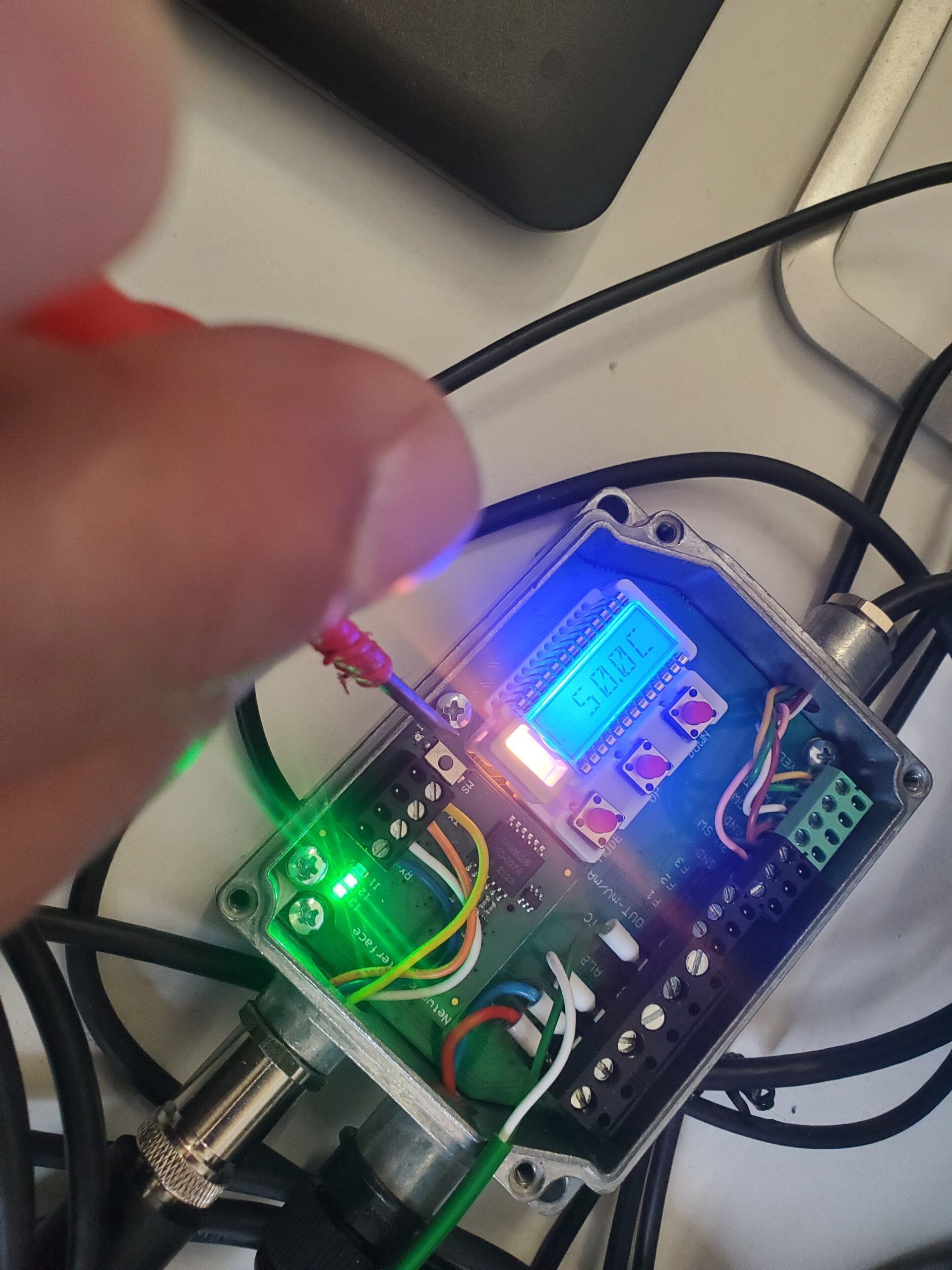
Here we have continuation of wiring with all the DC and control/PLC wiring.
This is the 6 Day milestone on this one-man control-cabinet build job.
Control Cabinet Build
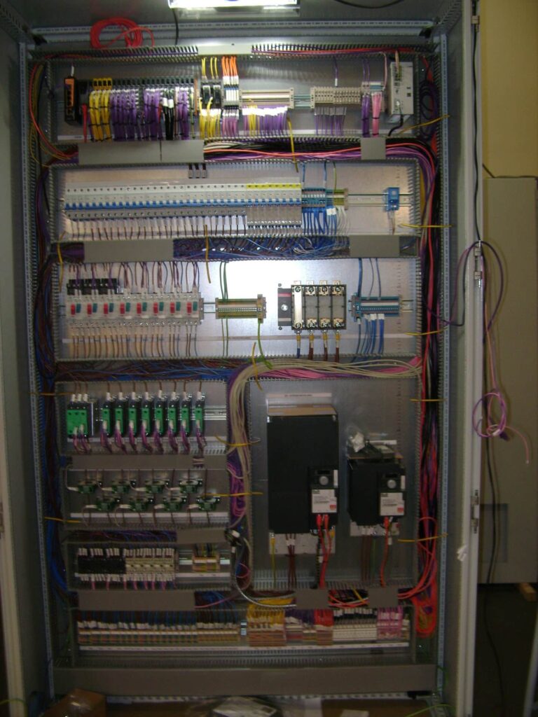
All wiring completed, awaiting trunking lid.

Control Cabinet Build
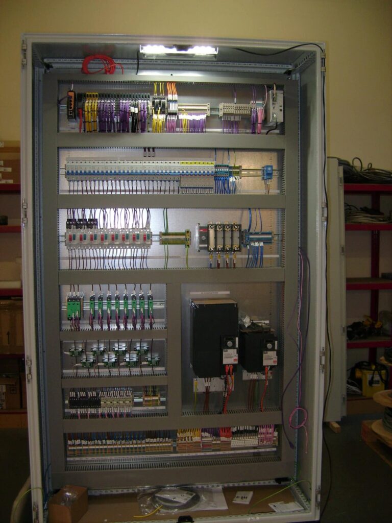
On Day 8 all trunking-lidding is complete.
It is now time to re-fit the panel doors.
Control Cabinet Build
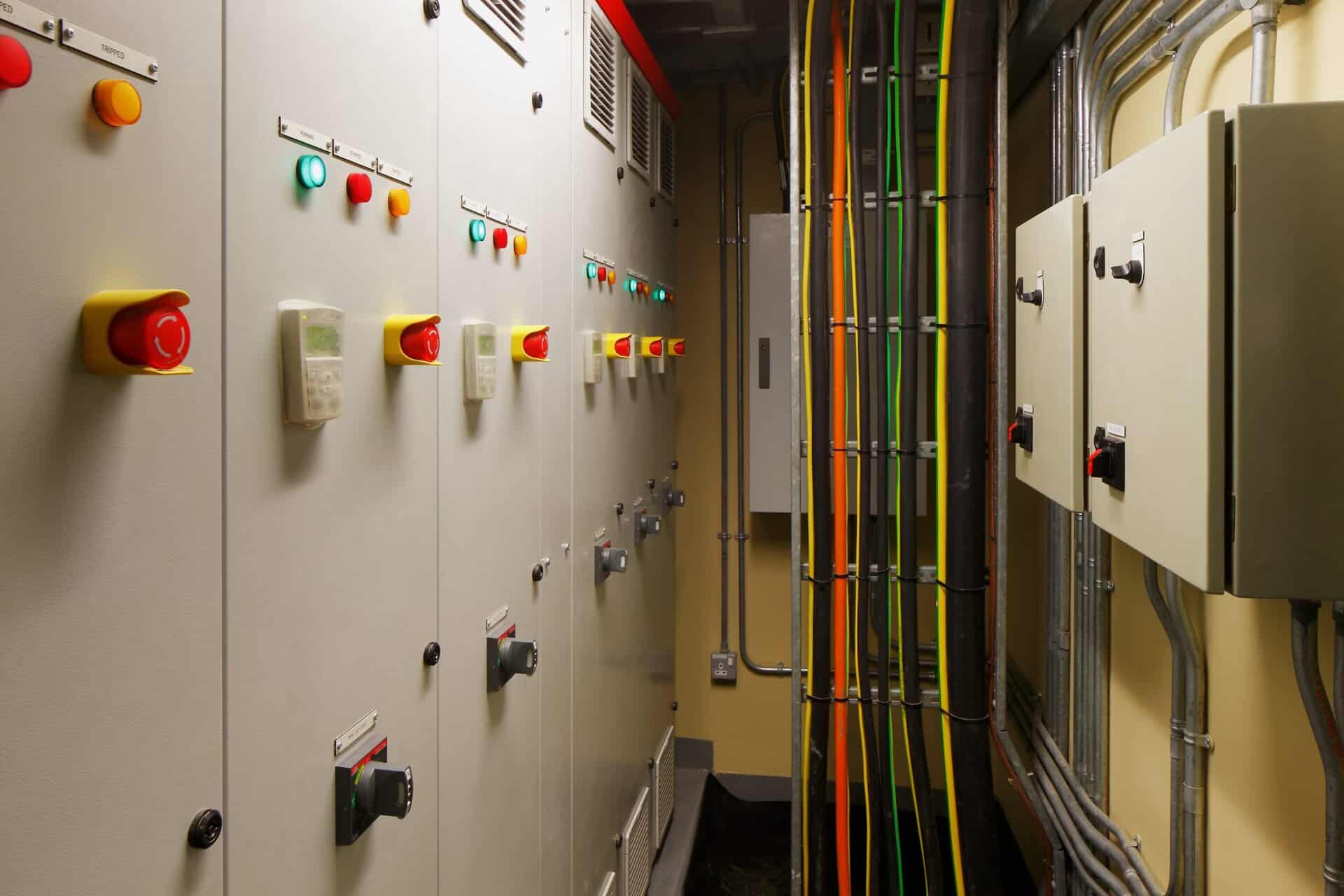
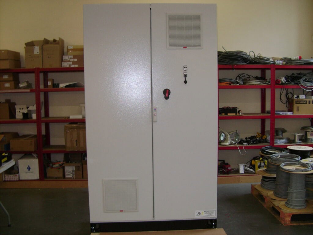
Panel doors fitted, you’ll note the fan used to moderate temperature inside this control cabinet.
There’s also a drawing-pocket mounted to the inside of a door as standard. This is where the most up-to date electrical drawings for the control cabinet will be stored, alongside completed Hardware Checklists prior to dispatch.
Control Cabinet Build
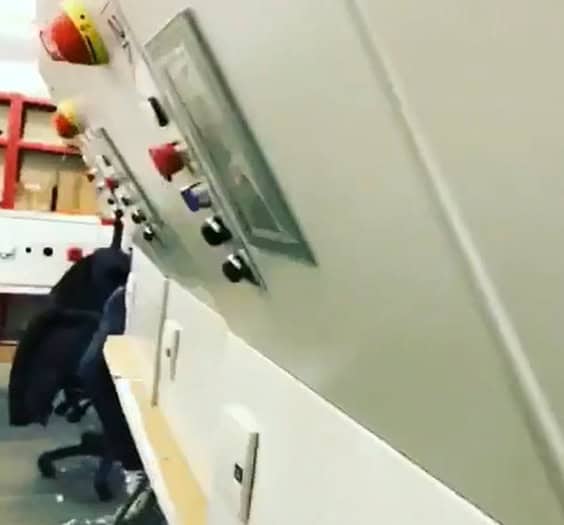
Ready for testing, here is the final photo on Day 9 to accompany this case study.
Can you notice the isolator-handle that is mounted to the control cabinet door?
Related Work
albums
albums
albums
albums
albums